HIGH-PERFORMANCE OPTICAL MEASUREMENT EQUIPMENT AND SYSTEM SOLUTION

TECHNICAL INFORMATION

(File C-1) WHAT IS "OPTICAL METHOD OPTICAL BEAM IRRADIATION AND DETECTION MEASUREMENT"?

OUTLINE

Synergy Optosystems proposes optical method optical beam irradiation and detection measurement, and is developing various types of "optical beam irradiation and detection measurement optics" products. In this content, explanation of our "optical beam irradiation and detection measurement", difference between another method, merits and demerits.

WHAT IS "OPTICAL BEAM IRRADIATION AND DETECTION MEASUREMENT"?

mscopetypei

In various optical measurement application, there are so many case to introduce optical beam, such as laser beam, LED light and so on, as probe beam onto the sample surface with high accuracy. For example, in case of measuring optical characteristic, such as light receiving sensitivity etc., of various light receiving elements, it is needed to introduce and irradiate probe beam onto the light receiving element accurately. Another case, of insertion loss measurement of various optical waveguide modules, it is needed to introduce and irradiate probe light to the core of incidence, and detect the transmitted light at the core of exit side accurately. Besides, there are supposed many other cases and applications, for example, to introduce probe light onto the bio cell, new material, and so on.

Previously, method to achieve probe beam introduction and irradiation onto the minute sample and detection of light from sample surface, is so-called optical fiber alignment method using optical fiber and light source. This is the method to search and decide the position of irradiate beam by moving optical fiber fixed on the slight movement mechanical stage system.

However, fiber alignment method has many weak points. First, it is impossible to recognize the accurate position of beam introduction and detection because there is no way to observe the position directly. Second, as the distance between sample and fiber incidence, the diameter and power of irradiating and detecting beam change. To search the ideal position of beam irradiation and detection, automatic (or manual) fiber alignment method by monitoring optical power is needed, but this task needs long time for accurate alignment inevitably.

OPTICAL METHOD OPTICAL BEAM IRRADIATION MEASUREMENT

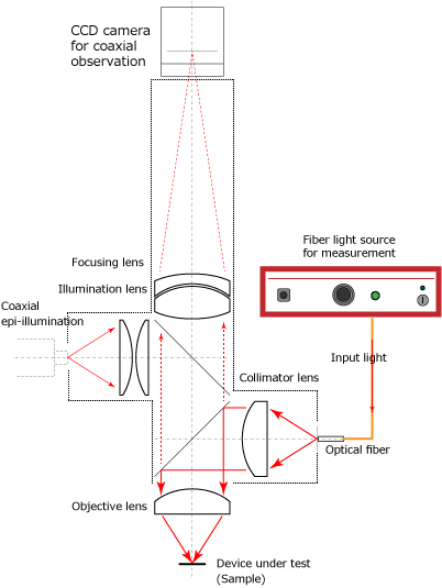
(Fig.1)Structure of optical beam irradiation optics

(Fig.2)Beam irradiation to the photo diode cell

As figure 1, simple structure of Synos' optical beam irradiation and detection optics is shown.

In case of beam irradiation measurement, optical beam from fiber output light source is irradiated onto the sample surface through optics. Optical beam from optical fiber connected to the optical fiber connect port travels along the red arrow in figure 1, and finally focused and irradiated onto the sample surface at the focal plane of the objective lens. At this time, irradiated beam diameter is decided as the core diameter of connected fiber onto the target sample surface with 1:1 magnification (using 10x objective lens). For example, in case SMF (10um core diameter) is connected to the fiber connect port, beam of 10umφ diameter is irradiated onto the sample surface. In this way, the same size optical beam as the fiber core connected to the fiber connect port is irradiated onto the sample surface through optics.

On the other hand, image of sample surface and irradiated beam condition can be monitored directly and simultaneously by the coaxial observation CCD camera as shown figure 1. Due to this function, irradiation beam position and condition can be checked by image directly and easily.

The image 1 shown left is observed image of irradiated beam onto the light receiving element (Si photo diode). The red point of center of the image is the irradiating point of optical beam. The condition of the sample in detail is shown below.

  • Sample : silicon photo diode
  • Objective lens : 10x
  • Light source : 850nm SLD light source
  • Input fiber : SMF (core diameter : <10um)

Additionally, diameter of irradiated beam can be changed as

  • change optical fiber (change the core diameter)
  • change objective lens (change the magnification ratio)

As above-mentioned, as using Synos' optical beam irradiation measurement optics, it becomes very easy and reliable to introduce and irradiate optical beam at the aiming point on the sample surface by confirming the position by observing image directly, even if the aiming point is very small. Additionally, in combination with this method and image processing, automatic alignment system, inspection efficiency improved remarkably.

For the reason as above, this method is especially good for the application shown below.

  • Optical characteristic measurement of light receiving element such as photo diode, light sensor, etc.
  • Insertion loss measurement of various waveguide module
  • Inspection of polymer optical waveguide for OPCB substrate
  • Light introduce research for bio cell sample, etc.

OPTICAL METHOD OPTICAL BEAM DETECTION MEASUREMENT

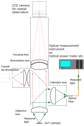
(Fig.3)Structure of optical beam detection optics

In case of beam (measured light) detection measurement, the beam (measured light) from the sample surface is relayed to the fiber core connected to the optical fiber connect port. The light emitted from sample surface travels along the green arrow in figure 2, and finally focused and relayed to the fiber core connected to the optical fiber connect port. At this time, detection area on the sample surface is decided as the diameter equivalent to the core diameter of conected fiber with 1:1 magnification (using 10x objective lens). For example, in case MMF (50um core diameter) is connected to the fiber connect port, the measured light in the area of approx. 50umφ diameter is relayed to the optical fiber. In this way, the same size of the detection area as the fiber core connected to the fiber connect port is measured and detected through optics.

As the same method as beam irradiation, image of sample surface and emitted beam condition can be monitored directly and simultaneously by the coaxial observation CCD camera as shown figure 1. Due to this function, measured beam position and condition can be checked by image directly and easily.

Additionally, diameter of measurement area can be changed as

  • change optical fiber (change the core diameter)
  • change objective lens (change the magnification ratio)

As above-mentioned, as using Synos' optical beam detection measurement optics, it becomes very easy and reliable to introduce and measure emitted light at the aiming point on the sample surface by confirming the position by observing image directly, even if the aiming point is very small. Additionally, in combination with this method and image processing, automatic alignment system, inspection efficiency improved remarkably.

For the reason as above, this method is especially good for the application shown below.

  • Insertion loss measurement of various waveguide module
    • Especially useful for hyperfine structural optical device such as Si(silicon) photonics device, nearfield optical device, etc.
  • Inspection of polymer optical waveguide for OPCB substrate
  • Light receiving measurement from LD, various optical modules, etc.

RELATED PRODUCT INFORMATION

DOWNLOAD